صور المظاهر بواسطة MichaelJay. يتم التشغيل بواسطة Blogger.
أقسام المدونة :

السبت، 4 نوفمبر 2017

Explore Fascinating Geology of Lofoten Islands, Norway

It is probably going to be boring what you are going to read, but if you are a geologist, please continue reading.
 What started as a simple fun trip with some friends to Lofoten Islands in northern Norway, just became a unique geological experience. This, because I think that, as a geologist, it is completely impossible to separate fun from my profession while traveling. It's just amazing to mix your profession with your favorite hobby. 
Trying to understand the rocks, the configuration of the landscapes and their phenomena, is simply priceless.
Reinebringen Mountain, Norway.
View to the town of Reine and Fjords.
Photo Credits: J. Sebastian Guiral
This time I got completely impressed with the beauty of the Fjords in Lofoten (help: what is a fjord? well basically, a fjord is a narrow and deep channel that allows the sea to enter to the land. They can be several kilometers long, so they are often confused with rivers or lakes, and can reach great depths, exceeding 1000 m. These geomorphological units are the product of sea flooding of valleys created by glacial activity).
Reinebringen mountain, Reine, Norway.
View to the town of Reine and Kirkefjord. U-shaped valleys and geomorphological features associated with intense tectonic activity. Glacial lake
Photo Credits: J. Sebastian Guiral
Hiking through the perfectly carved U-shaped valleys left me speechless (above mentioned glacial valleys). In each valley, it was possible to appreciate the sediments associated with the activity of the glacier, that is, the Moraines (frontal and lateral), till and reworked proglacial sediments.

Skelfjord, Lofoten, Norway.
Photo Credits: J. Sebastian Guiral


In addition, the typical vegetation of Tundra is impressive (help: what is Tundra? In simple words, it is a biome characterized by the lack of trees, the soils are mainly covered with mosses and lichens, characteristic of circumpolar latitudes. The subsoil is almost permanently frozen). This vegetation covered the base of the mountain chains and snowy hills, contrasting in a perfectly artistic way and offering a breathtaking view. 
Å, Moskenes, Norway.
Mosses on Precambrian gneisses and migmatites.
Photo Credits: J. Sebastian Guiral
Reine, Lofoten Norway.
View to Reinefjorden and snowy peaks
Photo Credits: J. Sebastian Guiral
Hamnøy, Lofoten Norway. Snowy Peaks.
Photo Credits: J. Sebastian Guiral
Haukland beach, Leknes, Lofoten, Norway

Snowy Peaks at Hamnøy, Lofoten Norway.
Photo Credits: J. Sebastian Guiral
What about lithologies? Well, broadly all those landscapes are conformed by a Precambrian basement represented by an Archean and Paleoproterozoic metamorphic complexes of ortho- and paragneisses, intruded by anorthosites and suites of charnokite-granites. This basement is in tectonic contact with amphibolites and paragneisses, which were intruded by tonalitic magmas at 470 Ma. Subsequently, at the top of the sequence, in a rather complex structural context, volcano-sedimentary sequences are found, ranging from the Permian to the Paleogene. These volcano-sedimentary sequences are part of the sea floor between Greenland and Norway. All these units are in well-marked tectonic contacts.

Utakleiv Beach, Leknes, Lofoten, Norway.
Paleoproterozoic amphibolites and gneisses.
Photo Credits: J. Sebastian Guiral
Utakleiv Beach, Leknes, Lofoten, Norway.
Paleoproterozoic amphibolites and gneisses
Photo Credits: J. Sebastian Guiral 

Paleoproterozoic amphibolites and gneisses at Haukland beach, Leknes, Lofoten, Norway
Photo Credits: J. Sebastian Guiral 

Finally, in addition to the geological stuff, the sunsets, perfect beaches, rainbows, snowstorms, the strong rain and a whole bunch of climatic phenomena associated with these high latitudes, make the Lofoten Islands one of the places. I have enjoyed a lot being a geologist. 

Reine, Lofoten Norway.
View of Reinefjorden and snowy peaks
Photo Credits: J. Sebastian Guiral 

 This is what I like about this profession, trying to understand a bit about such a complex, beautiful and huge planet.

If you are a geologist and feel the same as me while traveling, let me congratulate you.
You have a beautiful profession!
Sebas enjoying rain in Å, Moskenes, Norway.
Photo Credits: J. Sebastian Guiral 
  
Sebas exploring Paleoproterozoic amphibolites and gneisses at Utakleiv Beach, Leknes, Lofoten, Norway.
Photo Credits: J. Sebastian Guiral 
About authorJ. Sebastian Guiral is a Geological Engineer from the National University of Colombia. He is currently pursuing his master's program in Georesources Engineering at the Luleå University of Technology in Sweden. He also has  studied at the University of Liege in Belgium and at University of Lorraine in France. As a geologist, he has worked in important engineering and research projects in his country, which include geomechanics of underground excavations, geodynamics and geomorphology. Currently, his interests are focused on economic geology, exploration, mining and mineral processing techniques. 
You can contact with J. Sebastian Gujral at sebasguiralv@gmail.com or at Instagram: @sebasguiralv

We are grateful to J. Sebastian Gujral for sharing his knowledge and adventures with us. You can also contribute share your geological adventures with us. See details here.

الأحد، 10 سبتمبر 2017

Oil drilling Rig

What is Rig?

Owais Khattak at
KCA deutag 72 Location Makori East 6 MOL well
A drilling rig is a machine intend to drill hole in the Earth crust. Drilling rigs are massive structures which are used to drill hole for water, oil or natural gas. For water the rigs can be small, moved easily by one person which are termed as auger. But for oil or natural gas motives it can be very huge structures as you can see in the picture where it seems small but is tall about 46 meters. Drilling rigs can be mounted on trucks usually used for water wells or shallow wells. Small to medium-sized drilling rigs are mobile, such as those used in mineral exploration drilling, blast-hole, water wells and environmental investigations. Larger rigs are capable of drilling through thousands of metres of the Earth's crust, using large "mud pumps" to circulate drilling mud (slurry) through the drill bit and up the casing annulus, for cooling and removing the "cuttings" while a well is drilled. Hoists in the rig can lift hundreds of tons of pipe. Other equipment can force acid or sand into reservoirs to facilitate extraction of the oil or natural gas; and in remote locations there can be permanent living accommodation and catering for crews (which may be more than a hundred). Marine rigs may operate thousands of miles distant from the supply base with infrequent crew rotation or cycle.
As you see the rig in the picture where I stands with it, its a huge structure which is intended to drill deep into the Earth crust. This rig is 2000 horse power and able to drill deep because it can lift huge weight of the drill pipes. 

Rig components

Rig is basically made up of five components without which a rig is incomplete which will be discussed below and the components are
  1. Power
  2. Circulation system
  3. Hoisting system
  4. Rotation 
  5. Blowout preventer (BOP)

Power

A rig is always operated with some energy for the whole of the rig to operate which can be generated through some generators or by placing engines. The rig above was using five generators where three were operational for the rig every time because one cannot stop the rig it costs the operation and two were as backup engines. The power is necessary for a rig or its just a tall standing structure.

Circulation system

Circulation system in terms of rig is mud (slurry) which is made up of mud, water or oil which ever type of mud is required for the subsurface formation, and mixture of chemicals which includes gel, barite for increasing weight, caustic soda, defoamation etc. The mud is pumped from the mud tanks by mud pumps and travels through pipes into drill pipes which goes all the way down into the hole in pipes and gets out through holes in bit and returns to surface via annulus. Annulus is the inner diameter of the hole from which mud comes out to the surface bringing cuttings from the bore hole and creating mud cakes around the hole walls. The mud when comes out of the hole it goes to shakers where mud and well cuttings are separated. The mud also exerts hydrostatic pressure on the formation so that any fluid or gas from formation doesn't enters the bore hole.
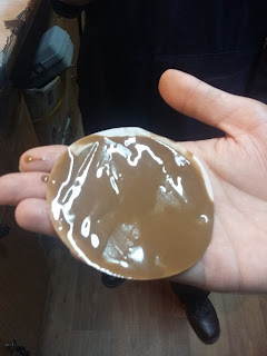
Mud cake (1mm) produced in the lab with currently used mud which depicts the inner hole scenario.

Hoisting System

Hoisting system is done by the top drive system (TDS) which is held by strings and pulleys atop. The hoisting system is responsible for lifting the heavy weight of the drill pipes. If you cannot pull out or run in the drill pipes you cannot drill the hole. 

Rotation

Rotation refers to the rotation of drill pipes which in turn rotates the drill bit deep down the hole and cuts the formation. As the drill bit rotates and cuts the formation, if cuttings are not removed from the deep down hole the drill bit can stuck. If not stuck the drill bit will further be crushing the cutting and not the formation this is where the mud works comes in. It lifts up the cutting so that it can drill further and also cools down the bit as friction heats it up and deep the Earth itself is hot.

Blowout preventer (BOP)

BOP is the equipment installed at the surface where drill strings goes in it. The blowout preventer as the name itself is explanatory is used to stop the blowout. The BOP is 1, 2 or 3 stages preventer which is composed or either annulus ram and shear rams, annulus ram, shear rams or upper pipe ram or annulus ram, shear rams, upper pipe ram and lower pipe ram. The BOP is used when the formation pressure exceeds the hydrostatic pressure or else the fluid from the formation will enters the well which is termed as kick. When the kick reaches the surface it will blowout everything within and the rig itself so in order to stop that BOP is installed so that it can stop the pressure from coming out the hole.
BOP

الأربعاء، 21 يونيو 2017

Fault anatomy

Fault anatomy

Faults drawn on seismic or geologic sections are usually portrayed as single lines of even thickness. In detail, however, faults are rarely simple surfaces or zones of constant thickness. In fact, most faults are complex structures consisting of a number of structural elements that may be hard to predict. Because of the variations in expression along, as well as between, faults, it is not easy to come up with a simple and general description of a fault. In most cases it makes sense to distinguish between the central fault core or slip surface and the surrounding volume of brittlely deformed wallrock known as the fault damage zone, as illustrated in Figure 8.10.
Simplified anatomy of fault.
The fault core can vary from a simple slip surface with a less than millimeter-thick cataclastic zone through a zone of several slip surfaces to an intensely sheared zone up to several meters wide where only remnants of the primary rock structures are preserved. In crystalline rocks, the fault core can consist of practically non-cohesive fault gouge, where clay minerals have formed at the expense of feldspar and other primary minerals. In other cases, hard and flinty cataclasites constitute the fault core, particularly for faults formed in the lower part of the brittle upper crust. Various types of breccias, cohesive or non-cohesive, are also found in fault cores. In extreme cases, friction causes crystalline rocks to melt locally and temporarily, creating a glassy fault rock known as pseudotachylyte. The classification of fault rocks is shown in heading below.
In soft, sedimentary rocks, fault cores typically consist of non-cohesive smeared-out layers. In some cases, soft layers such as clay and silt may be smeared out to a continuous membrane which, if continuous in three dimensions, may greatly reduce the ability of fluids to cross the fault. In general, the thickness of the fault core shows a positive increase with fault throw, although variations are great even along a single fault within the same lithology. 
The damage zone is characterized by a density of brittle deformation structures that is higher than the background level. It envelops the fault core, which means that it is found in the tip zone as well as on each side of the core. Structures that are found in the damage zone include deformation bands, shear fractures, tensile fractures and stylolites, and Figure below shows an example of how such small-scale structures (deformation bands) only occur close to the fault core, in this case defining a footwall damage zone width of around 15 meters.
Damage zone in the footwall to a normal fault with 150–200 m throw. The footwall damage zone is characterized by a frequency diagram with data collected along the profile line. A fault lens is seen in the upper part of the fault. Entrada Sandstone near Moab, Utah.
The width of the damage zone can vary from layer to layer, but, as with the fault core, there is a positive correlation between fault displacement and damage zone thickness (Figure below a). Logarithmic diagrams such as shown in Figure below are widely used in fault analysis, and straight lines in such diagrams indicate a constant relation between the two plotted parameters. In particular, for data that plot along one of the straight lines in this figure, the ratio between fault displacement D and damage zone thickness DT is the same for any fault size, and the distance between adjacent lines in this figure represents one order of magnitude. Much of the data in Figure below a plot around or above the line D=DT, meaning that the fault displacement is close to or somewhat larger than the damage zone thickness, at least for faults with displacements up to 100 meters. We could use this diagram to estimate throw from damage zone width or vice versa, but the large spread of data (over two orders of magnitude) gives a highly significant uncertainty. 
A similar relationship exists between fault core thickness (CT) and fault displacement (Figure below b). This relationship is constrained by the straight lines D=1000CT and D-10CT, meaning that the fault core is statistically around 1/100 of the fault displacement for faults with displacements up to 100 meters.
(a) Damage zone thickness (DT) (one side of the fault) plotted against displacement (D) for faults in siliciclastic sedimentary rocks. (b) Similar plot for fault core thickness (CT). Note logarithmic axes. Data from several sources.
Layers are commonly deflected (folded) around faults, particularly in faulted sedimentary rocks. The classic term for this behavior is drag, which should be used as a purely descriptive or geometric term. The drag zone can be wider or narrower than the damage zone, and can be completely absent. The distinction between the damage zone and the drag zone is that drag is an expression of ductile fault-related strain, while the damage zone is by definition restricted to brittle deformation. They are both part of the total strain zone associated with faults. In general, soft rocks develop more drag than stiff rocks.

Fault rocks

When fault movements alter the original rock sufficiently it is turned into a brittle fault rock. There are several types of fault rocks, depending on lithology, confining pressure (depth), temperature, fluid pressure, kinematics etc. at the time of faulting. It is useful to distinguish between different types of fault rocks, and to separate them from mylonitic rocks formed in the plastic regime. Sibson (1977) suggested a classification based on his observation that brittle fault rocks are generally non-foliated, while mylonites are well foliated. He further made a distinction between cohesive and non-cohesive fault rocks. Further subclassification was done based on the relative amounts of large clasts and fine-grained matrix. Sibson’s classification is descriptive and works well if we also add that cataclastic fault rocks may show a foliation in some cases. Its relationship to microscopic deformation mechanism is also clear, since mylonites, which result from plastic deformation mechanisms, are clearly separated from cataclastic rocks in the lower part of the diagram. 

Fault breccia is an unconsolidated fault rock consisting of less than 30% matrix. If the matrix fragment ratio is higher, the rock is called a fault gouge. A fault gouge is thus a strongly ground down version of the original rock, but the term is sometimes also used for strongly reworked clay or shale in the core of faults in sedimentary sequences. These unconsolidated fault rocks form in the upper part of the brittle crust. They are conduits of fluid flow in non-porous rocks, but contribute to fault sealing in faulted porous rocks.
Pseudotachylyte consists of dark glass or microcrystalline, dense material. It forms by localized melting of the wall rock during frictional sliding. Pseudotachylyte can show injection veins into the sidewall, chilled margins, inclusions of the host rock and glass structures. It typically occurs as mm- to cm-wide zones that make sharp boundaries with the host rock. Pseudotachylytes form in the upper part of the crust, but can form at large crustal depths in dry parts of the lower crust. 

Crush breccias are characterised by their large fragments. They all have less than 10% matrix and are cohesive and hard rocks. The fragments are glued together by cement (typically quartz or calcite) and/or by microfragments of mineral that have been crushed during faulting.
Cataclasites are distinguished from crush breccias by their lower fragment–matrix ratio. The matrix consists of crushed and ground-down microfragments that form a cohesive and often flinty rock. It takes a certain temperature for the matrix to end up flinty, and most cataclasites are thought to form at 5km depth or more. 
Mylonites, which are not really fault rocks although loosely referred to as such by Sibson, are subdivided based on the amount of large, original grains and recrystallised matrix. Mylonites are well foliated and commonly also lineated and show abundant evidence of plastic deformation mechanisms rather than frictional sliding and grain crushing. They form at greater depths and temperatures than cataclasites and other fault rocks; above 300 C for quartz-rich rocks. The end-member of the mylonite series, blastomylonite, is a mylonite that has recrystallized after the deformation has ceased (postkinematic recrystallization). It therefore shows equant and strain-free grains of approximately equal size under the microscope, with the mylonitic foliation still preserved in hand samples.
Credits: Haakon Fossen (Structural Geology)

Interested for our works and services?
Get more of our update !